Objective:
Learn how to set up and create a patch cable, install RJ 45 connectors on an existing cable, then use the tester to test the cable and make sure that it works out.
Equipment:
CAT-5e Ethernet cable, Spare cable was used to make the connections.
RJ 45 Modular Plug Connectors were used making the cable.
Klein Tools VDV501-825 VDV Scout Pro 2 LT Tester: To verify the wires were connected and the cable was working this tester was used.
RJ 45 Networking cable stripping tool was used to expose the wires
RJ 45 Network cable crimping tool: Once the wires were arranged in the proper order we slid on the Modular Plug carefully then used the crimping tool to make sure the plug in connectors were crimped on the cables.
CAT 5 Punch down tool: this tool was used to put the wires into the wall jack plug and patch panel.
CAT 5e panel & wall jack:
Scissors: these were used to cut the old Plugs off the end of the cable and to cut the fibers inside of the cable.
NOTES:
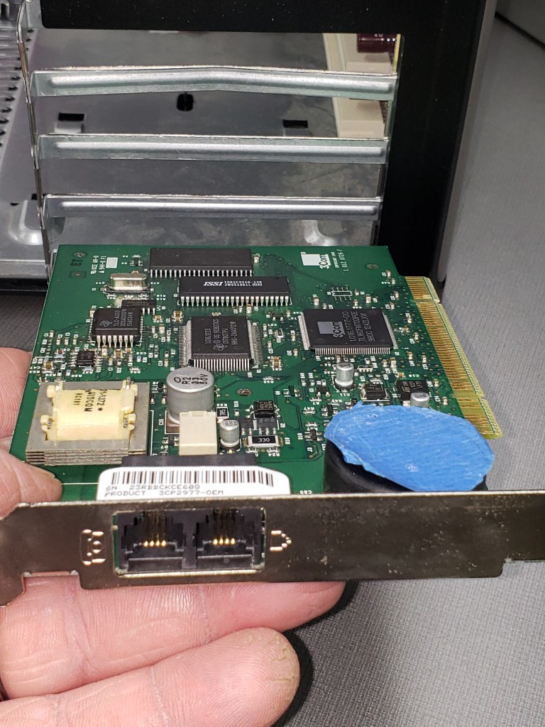
In the lab introduction, different kinds of networking media were introduced including Thick & Thin Ethernet, vampire taps, multi-mode fiber optics, and CAT 5e. A older Network Interface Card was passed around.I first started the lab by selecting a RJ 45 CAT 5e cable from the desk then cutting off an end with scissors. The wire stripping tool was then used to strip off of the outer insulation of the cable. Next with the instruction of Lab mate Mike Hendricks, I put the wires in order of the T568B Wiring Standard. I estimated the length needed and cut off of the extra, and with the wires in the correct order i slide the wires in the Modular plug. After verifying the correct order i then used the crimping tool to attach the end on the wire. I then tested the cable using the cable tester and found that only two of the eight wires weren’t working. I then cut the end of the plug off and redid the process getting it correct the second time. The cable then worked as expected. Ethan then wired the other end of the CAT5 cable. Then I moved on to the next project of the lab by getting another spare cable from the desk and cut off both ends. After using the wire stripper to take off the outer insulation. I wired the wall jack on one side of the cable and used the punch tool to make sure the wires were connected correctly to the jack. Mike then wired the one port of the patch panel to the other side of the cable. Finally, mike tested the cable and verified that it worked using the network cable tester.It was pretty straight forward to make the CAT 5e Ethernet cable by following the instructor’s directions and the directions on the handout and lab mate mike. I think that it will be useful in the future to know how to make network cables, connect the cables to a patch panel, connect them to wall jacks, and verify the cable works using a cable tester.
Conclusions:
This particular lab I accomplished making a network cable by placing the modular plugs on the end of the wires, also attached the cable to a wire jack and a patch panel. It will be useful to know how to do this when i get to point of wanting to build and design the Network for the home.